|

| Print this page - use Landscape |
Search the WeetHet Pages |
||||||||||||||||||||||||||||||||||||||||||||||||||||||||||||||||||||||||||||||||||||||||||||||||||
| WeetHet is being updated! - Current articles will slowly move to www.tweaking4all.com For excellent webhosting that is reliable and affordable, we highly recommend: LiquidWeb |
|||||||||||||||||||||||||||||||||||||||||||||||||||||||||||||||||||||||||||||||||||||||||||||||||||
|
On this page...
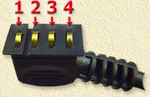
Garmin eTrex connector Below you will find the connector pinout of the Garmin eTrex connector:
You will need this info to hook your eTrex to a PDA or PC. The serial interafce comes in two froms, a 9-pin variant and a (older) 25-pin variant, both are connected as shown below:
Note: In the RS232 column you will find two sub-columns called 9-pin and 25-pin, refering to the two RS232 connector variants. The 9-pin variant is the most common one. Tip: If you're busy with an eTrex connector anyways then you might want to consider adding external power for the eTrex aswell. Use a 3V powersupply and connect it to pin 1 (+) and 4 (-) of eTrex connector. The RS232 DB9 connector This is a well known and well document connector, most of them even have numbering on the connector itself.
Below you will find tables of both variants of the serial connector. Note: These pinouts are identical for both male and female connectors! Note: Notice the swap op pin 2 and 3 if you compare both connectors!
|
|||||||||||||||||||||||||||||||||||||||||||||||||||||||||||||||||||||||||||||||||||||||||||||||||||